CONCEPTUALIZATION


Following the ideation phase, the defined solutions were worked out in detail. This phase entails the three separate concepts that all together, make the process of attaching/detaching his hand bike relatively easier for him. As the CO wishes to be more independent, emphasis was placed on creating solutions that make the entire process as effortless as possible for him.
COUPLING
Simplistic ramp
Why a ramp?
The ramp was designed to be a simplified alternative solution to the second problem encountered by the case owner in the coupling process, that being having to put force into the handlebars to lock the hand bike in place.
Without using the ramp, the CO must counter the following three forces when coupling the hand bike:
-
Tipping his own weight and the weight of the wheelchair backwards.
-
Tipping the weight of the hand bike forwards
-
The force of the spring in the coupling mechanism
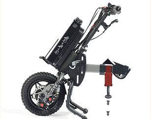
By driving up the ramps with the two small wheels, located under the footboard of the hand bike, before coupling, the front wheel of the hand bike lifts off the ground. This means that instead of having to overcome the weight of the hand bike, that weight now aids in the coupling process, significantly reducing the force required.
Why the simplified prototype
A simplified prototype for the ramp was created as a smaller part of the project, instead of remaining a main focus for the following reasons:
-
The case owner expressed discomfort towards the idea of performing the tipping motion with the wheelchair.
-
The ramp would only offer a solution for coupling at home.
-
Uncertainty on the probability of the ramps working during testing
-
The size of the prototype would make it difficult to produce
-
Shortage of time and abundance of other paths
-
The simple but technical nature of the concept left little room for co-design.
Since the design had progressed far enough to make a working prototype, and there being a chance to allow the case owner to couple the hand bike independently using it, the choice was made to manufacture a proof-of-concept prototype. If the prototype would prove functional, a more elaborate prototype could be made for the CO outside of project time.
Original design
The original design was simplified for the eventual prototype since it would have required too many resources to merit its realization.
-
It would have consisted of 4 elements. Two ramps for the small wheels on the handbike, one ramp to ensure grip on the front wheel when driving up and one smaller connector for structural rigidity.
-
The ramp would have be produced in 9 separate, interlocking, parts to fit the 3d printers available at the UT.
-
The 2 ramps for the smaller wheels would feature a concave shape to help with aligning the wheelchair and handbike properly with the ramp.
-
The interlocking parts would allow for a modular setup (for instance, to remove the front wheel ramp or one of the slopes if they proved unnecessary)
Simplified prototype
-
The simplified prototype is made out of laser cut wood since this could be manufactured more easily and quickly.
-
The ramp for the front wheel was discarded, reducing production time.
-
The concave shape was removed due to it being impossible to manufacture with lasercut wood
-
The ramp was redesigned without the “downward” rear section to make it easier to use momentum to stay on top of the surface.
Jack
Why a Jack?
As mentioned, there were two concepts for a coupling mechanism, these were a ramp and a jack. Because of the following reasons the jack was chosen:
-
It is portable.
-
It costs less force than the coupling now, and if made electric, the only force is pressing a button.
-
The same movement is made as when coupling now, with the assistance of a parent, which makes that the case owner does not need to step outside of his comfort zone.
Why this kind of jack?
There are multiple options to make a jack. The reasons why this kind of jack was chosen are the following:
-
It has an easy mechanism
-
It is stable
-
It is small and fits nice on the wheelchair
Why not a real size working model?
Only a scale model is made for prototyping for this project. This is because the motor needed to get the amount of force it takes to couple the hand bike to the wheelchair with a jack is way too expensive and out of reach for the project group to prototype with. Also, the number of calculations and safety restrictions that need to be made to let it work and be safe take way too much time, which is not available in this project.
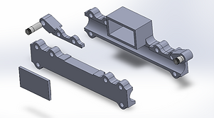
prototype rationale
-
The box is longer so the distance between the ground and the start of the jack is less, which makes it less unstable.
-
To use a simple mechanism, the extra space on the long side of the box is useful since it makes that the straight gear, which moves down and moves the wheelchair up from the ground, can take that space.
-
It only acquires 2 gears and 1 motor.
-
The ‘tooths’ of the wooden outside are to make it strong and easy to assemble.
-
The gears are 3d-printed to have less resistance.
-
The hole on the side, number 1, is for wires to come out.
-
The little box, number 2, on the inside is for the battery to sit in. However, this has not been placed in the end since a power outlet is used.
-
The plate, number 3, is for the motor to lie on. However, in the end this has not been placed since a bigger motor is used
-
The plates in the middle, number 4, are there to keep the gears in place.
-
The hook on the bottom makes the connection between the jack and the ground stable when used.
-
One thing is changed from the SolidWorks model. This is the size of the slot where the motor sits. This because in the end a bigger motor was used, so it was sawed by hand, to let it fit.
Decoupling
DECOUPLER
Problem description
The current mechanism for detaching the handbike from the wheelchair is insufficient as it requires a significant amount of force to activate. Moreso than the case owner is able to comfortably output. The current solution is the brake lever from a bicycle that has been attached to the main beam of the handbike, pulling a cable to release a spring loaded mechanism. Due to the friction in the system combined with resistance of the spring and the pressure from the weight of the user it is very difficult to release. Hence, after identifying this as an issue, we aimed to create an effective solution.
In order to produce a suitable product, we needed to ensure that it sufficiently addressed the design challenge and was specific to the user and their needs.
POTENTIAL SOLUTIONS
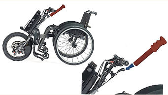
When addressing the design challenge, two main proposals were conceived. Both approaches are methods to generate more leverage; which were redesigning the lever itself or creating a removable attachment (Figure 2 & 3).
The redesigned lever benefited from having the capacity to be a more neatly integrated solution, however, demanded a significant degree of intricacy in manufacture.
The handle attachment would be simple and inexpensive to manufacture, reduces bulk on the handbike and remain unobtrusive when not in use. However, it does require separate storage.
WHY THIS SOLUTION?
Ultimately, the attachment was selected as it offers more flexibility in its use whilst leaving the handbike less bulky when not attached, as well as the ease of manufacture.
DESIGN DEVELOPMENT
Throughout the development of the decoupler, multiple iterations were created and explored. Each aiming to adhere to the following requirements:
-
Reduce the force required to release the locking mechanism
-
Remain removable from the handbike
-
Be comfortable to use
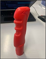
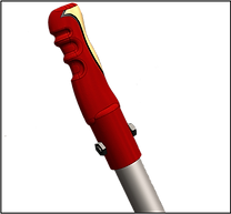
The underlying design of the decoupling device is relatively straightforward and effective in achieving the first two goals. To create a more enjoyable user experience, a custom handle was also designed.
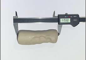
During the co-design process a clay mould was taken of the case owner’s grip which was then modelled in CAD software to produce a handle that could be made via additive manufacturing processes .
Once measurements were taken of the existing lever, three separate prototypes, varying by overall length and locator position, were made and tested to ensure accurate alignment and successful function.
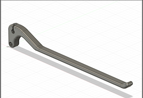
FINAL DESIGN
The final design consists of a 20x2mm steel tube the base of the tube. This was found to be the most suitable combination as it provided sufficient leverage and was easy to locate accurately (Figure 7).
The handle was 3D printed due its accessibility, cost and accuracy.
The 3D printed handle is attached to the top of the tube via a single nut and bolt passing through the entire assembly. This was done to ease prototyping but could be refined in the future through the use of rivets or a recessed bolt/screw.
alignment
Laser bracket
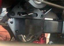
The laser bracket is a solution to the first problem encountered by the
case owner when coupling the hand bike to the wheelchair. The
connecting bar of the hand bike needs to be pulled accurately onto a
bracket mounted, out of view, underneath the wheelchair. During the
second co-design session, when demonstrating the coupling
again, it became clear that this alignment also posed a challenge to
the case owner.
The problem consists of two key factors:
-
The connecting bar on the hand bike only just fits onto the
bracket under the wheelchair, meaning it has to be aligned with
great accuracy.
-
The connecting bar has to have a bit of momentum to clear the
bracket to allow for the next stage in the coupling process.
The focus was on solving the alignment issue, since that is most
feasible and would make it easier to gain the momentum needed.
Options
Three different options were considered as solutions for this problem. In the following, the options and the reasoning for the chosen option are presented.
1. Stationary alignment guide
The first idea was to have a guide that would be on the floor when aligning the hand bike to the wheelchair. This might have been incorporated in the ramp coupling concept. The idea was to have something that would make “aiming” easier for the case owner by providing a guide track for the hand bike and a place for the wheelchair to sit steadily.
Pros:
-
A simple prototype might be possible
-
No need for moving parts
-
No need to mount anything to the wheelchair or hand bike
Cons:
-
It cannot be made mobile (so case owner could only use it at home)
-
May be in the way at the next coupling stage
-
The prototype would be quite large
2. Mounted alignment guide rail
The second idea was to have a strong metal guide rail mounted to the bracket underneath the wheelchair to act as a funnel that guides the coupling bar onto the bracket.
The triangle seen in the model would fit over the triangle shape of the bracket. With the top circles going over the bar that connects the bracket to the wheelchair (that can be removed, since it is not original to the wheelchair but attached to allow for the hand bike to connect). The 4 smaller holes allow for new, longer bolts, to be used to securely attach the rail.
Pros:
-
It is mobile since it would stay attached to the wheelchair, allowing the case owner
to use it when out independently.
-
The product would be user friendly, as the case owner would not have to spend any
effort on aligning.
-
The product would be applicable for a wider audience, since it is relevant to all
Batec-handbike users.
Cons:
-
Having to mount something to the wheelchair may not be possible due to regulations regarding wheelchair modification and available room.
-
Manufacturing the prototype on short notice poses a significant challenge because it needs to be strong enough to resist the metal coupling bar smashing into it.
-
The mechanical nature of the solution leaves no room for co-designing something appealing to the case owner.
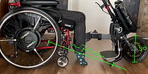
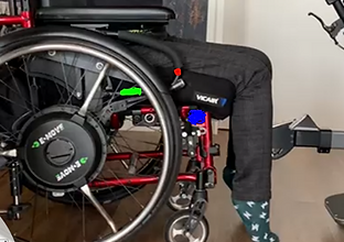
3. Laser bracket
The third option considered was using line lasers that display a line on the floor when a button is pressed, to offer a visual aid to the case owner when aligning the hand bike. The case owner would then be able to drive over the lines with the small plastic wheels of the hand bike, making the alignment much easier.
The displayed model is of 2 separate laser brackets that would be mounted underneath the horizontal tube of the wheelchair (as seen on the left side of the “70 cm” line).
Pros:
-
matches up with preferences expressed by the case owner during the co-design session.
-
It is mobile since it would stay attached to the wheelchair, allowing the case owner to use it when out independently.
-
No need to modify the wheelchair or hand bike (lasers and switch can be attached temporarily)
-
Feasible for prototyping
Cons:
-
The lasers that are key to the solution will have to be sourced, and may not be powerful enough.
-
The case owner would still have to align the hand bike manually since this is just a visual aid.
Choice
After weighing and discussing the pros and cons. The laser bracket was chosen as the best solution to keep developing. The key factors in this decision were the fact that it fit the goal of the project and would be most aligned with the preferences expressed by the case owner during the co-design sessions.
Laser Bracket development
During the development of the Laser bracket, various solutions were considered to address the attachment, functionality and manufacturability of the prototype.
The main aims during this phase were:
-
Maximize attachment freedom, to allow for on the fly adjustment during testing.
-
Reduce possible manufacturing difficulties by considering available resources during the design process.
The following goes into design decisions made, and their rationale.
Nuts and bolts
The final design features nuts and bolts to clamp the two main structural parts of the laser bracket over the tube of the wheelchair. This would allow for a secure, but removable attachment to the wheelchair that could be adjusted on the fly.
The other option that was considered was using elastic bands or tie wraps around brackets with space for them. This option was discarded as nuts and bolts would offer a sturdier and more adjustable solution. The example on the top would be mounted more forward, attached with elastic bands or tie raps around the forward facing tubes of the wheelchair, and the example on the bottom would be one of two brackets holding a single laser attached to the horizontal tube.
One bracket around horizontal tube
The final design is a single bracket, that is mounted around the existing horizontal tube of the wheelchair. The other options considered were:
-
Two separate brackets mounted to the horizontal tube.
-
A single bracket, braced in front of the horizontal tube.
The advantage of two separate brackets would be the additional freedom of attachment, since this way the spacing between the lasers could be manipulated during testing. The disadvantage of this is the additional possible difficulties that would be encountered during manufacturing and attachment.
The advantage of the single bracket, braced in front of the horizontal tube, would have been to have the lasers closer to the place where they would have to project. A disadvantage of this might have been that it could interfere with the legs of the case owner, additionally the design in the shown form would not allow for adjusting the angle of the lasers. After analyzing the strength of the lasers and concluding that they are strong enough, this idea was discarded.
The final design that featured a single bracket around the horizontal tube, offered a simple and robust solution that still had all the necessary axis of adjustment to properly fit the lasers to the wheelchair.
Square shaped bracket
The final design features a bracket that was square in shape. This decision was made to ensure ease of manufacturing when using a 3D printer, since this shape would not require any support material. It also offered a strong base to attach nuts and bolts to.
The other option considered was a round shape. A more streamlined design through the use of rounded edges would have created a more visually appealing and coherent product, considering it will be mounted on a round tube. The idea for the round tube was dropped in favor of a square tube to ensure manufacturability.
Separate laser holders
The final design features separate laser holders from the main structure of the bracket (seen as red in the prototype). These fit between the two main parts of the bracket and are held in place by the same bolts that connect the bracket itself. Because the lasers would have to be exactly 30 cm apart, the final design would not be able to fit standard UT 3D printers. Additionally, this would allow us to more easily adjust the positioning of the lasers by only having to produce new laser holders, instead of a whole new prototype if the lasers would have to be positioned differently.
Toggle switch
The final design features a toggle switch that is used to turn the lasers on and off. The 6 prong toggle switch has 2 empty prongs, the 2 middle prongs soldered to the plus and minus of the 9 volt battery, and 2 prongs soldered to the plus and minus of the lasers as seen in the diagram. The toggle switch is glued onto a bike-light bracket to be able to attach it freely to the round armrest tubes of the wheelchair. Shrink rubber seals are used as a safe barrier for the electronics.
Another available option would have been a momentary electrical switch (as seen on the right) which had the advantage of being more easily available, but the disadvantage of having to be pressed while aligning the handbike. This could have been solved by the use of an arduino, but this would in turn have made the prototype more complex and increased the risk of a lack of space within the electronics compartment of the prototype.
Switch placement
Several possible placements for the switch were considered during the design process, this placement would have to be defined relatively accurately before deciding upon the wiring lengths. The decision was made to mount the switch at the position marked red in the picture.
The picture shows the 3 places for mounting the switch that were considered.
Blue, on the frame of the wheelchair itself.
-
Medium for ergonomics
-
Sufficient space (not considering footrests)
-
Medium for ease of mounting
-
Easy cable routing
Green, on the straight part of the frame under the armrest
-
Bad for ergonomics
-
medium space between wheel and cushion
-
Easy for mounting because of straight bar
-
Medium cable routing
Red, on the front, curved part of the frame under the armrest
-
Best for ergonomics
-
Good space
-
Harder to mount, because of the curved tube
-
Harder for cable routing
The final design features the switch in the position marked as red, since the bike-light bracket paired with the toggle switch overcomes the issue of the harder mount and the ergonomics and safety of the case owner are key considerations.
The next step is making prototypes of these concepts and testing them. The prototypes itself, the test results and the reflection on the List of Requirements can be found on the ‘Results’ page.